B Draw a free-body diagram of the cushion and identify each force acting on it. C Identify all of the action reaction pairs of forces in the brickcushionplanet system.
Part A Draw a free-body diagram for the steel cable.

. A free body diagram is a diagram in which only the forces imposed on an object are shown. The location and orientation of the vectors will be graded. Imagine the body to be isolated or cut free from its constraints and draw its outlined shape.
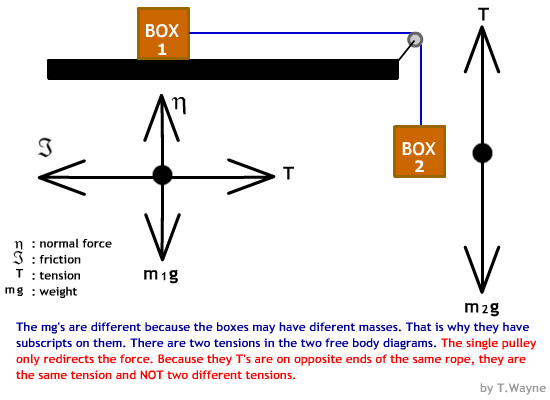
Because the stationary box is on a surface there is a normal force that acts perpendicular to the surface. Fgravity FtensionG on C Part B Draw a free-body diagram for the. FREE-BODY DIAGRAMS Section 52 2.
If your free-body diagram is incorrect then your equations analysis and solutions will be wrong as well. To one side in the CAD program construct the Free Body Diagram as shown in Figure 57. Free body diagrams are a simple tool to help us identify all of the forces that influence an object.
Draw the vectors starting at the black dots. Drawing a correct free-body diagram is the first and most important step in the process of solving an equilibrium problem. Drawing a force diagram with arrows having a labeled force type and the proper size.
Deciding upon the relative size of opposing forces 4. Based on your diagram which of the two ropes will have the greater tension. Draw an outlined shape.
A free-body diagram is a special example of the vector diagrams that were discussed in an earlier unit. A good free-body diagram is neat and clearly. F gravity F tension G on C.
B If the maximum tension either rope can sustain without breaking is 5000 N determine the maximum value of the hanging weight that these ropes. 20 The weight of the stationary box is 412 kg. Figure 44 shows various free-body diagrams that can be considered in the analysis of a crank slider mechanism.
Show all the external forces and couple moments. The following force convention is defined. The length of the vectors will not be graded.
DETERMINE THE AMOUNT OF NORMAL FORCES EXERTED ON THE CONTAINER. The length of the vectors will not be graded. The location and orientation of the vectors will be graded.
We will also draw in any forces or moments acting on the body including those forces and moments exerted by the. Identifying the types of forces acting on the object 2. We can see that both cables will share the load equally since the problem is symmetrical therefore we will draw a small triangle just below the Free Body Diagram.
Together they are sliding to the right at constant velocity on an ice-covered parking lot. It is the basis for all the equilibrium equations you will write. Draw a free-body diagram for the steel cable.
The spring has a length of 019 m an unstretched length of 023 m and a spring constant of 2507 Nm. Fij represents the force exerted by link i on link j. A applied loads b support reactions and c the weight of the body.
A Draw a free-body diagram showing all of the forces acting at the knot that connects the two ropes to the steel cable. Draw the free-body diagram of the crane boom AB which has a weight of 650 lb and center of gravity at GThe. Determining the direction of those forces 3.
Identify the forces acting on the box. A steel cable with mass is lifting a girder. The size of the arrow in a free-body.
The girder is speeding up. Idealized model Free-body diagram FBD 1. Our diagram should appear in the CAD software application as shown in Figure 57.
As the name suggests the purpose of the diagram is to free the body from all other objects and surfaces around it so that it can be studied in isolation. Up to 256 cash back A steel cable with mass is lifting a girder. A Draw a free-body diagram of the brick and identify each force acting on it.
A free-body diagram is a drawing of a part of a complete system isolated in order to determine the forces acting on that rigid body. Draw the free-body diagram of the truss that is supported by the cable AB and pin CExplain the significance of each force acting on the diagramSee Fig57b A B C 2 m 2 m 2 m 2 m 30 3 kN 4 kN 56. How to draw free body diagram.
Draw the vectors starting at the black dots. A free body diagram is a tool used to solve engineering mechanics problems. DRAW FREE BODY DIAGRAM.
µs 060 is the coefficient of static friction between the box. Free-body diagrams are diagrams used to show the relative magnitude and direction of all forces acting upon an object in a given situation. 10 Free body diagrams.
Method for Drawing Free-Body Diagrams The task of drawing a free-body diagram involves. Draw the object with no extra features. These diagrams will be used throughout our study of physics.
The box has mass so it should also have weight and a force acting downward. In this tutorial well cover free body diagrams and how to use them to evaluate the forces acting on a structure in equilibrium.

Free Body Diagram Showing The Total Forces On The Sliding Block The Download Scientific Diagram

A Deformation Of A Three Tower Suspension Bridge B Free Body Download Scientific Diagram

How To Draw A Free Body Diagram Simply Supported Beam With A Point Load Youtube

Free Body Diagram An Overview Sciencedirect Topics

Handgemaakt Industrieel Tafelonderstel X Poot Zwaar Kruispoot Zwart Mesas De Comedor Mesas De Comedor Industriales Patas De Mesa


0 comments
Post a Comment